
|
Microscope - Basic Illumination Settings > Dr. Probe / Documentation / GUI / Microscope / Illumination |
|
Basic illumination parameters are relevant for the electron probe formation The meaning of each parameter is described separately on this page below.
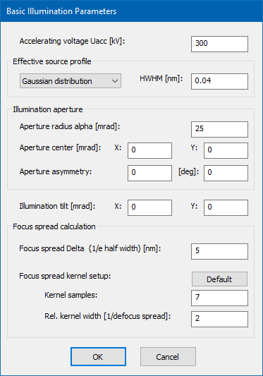
The accelerating voltage Uacc of the microscope determines the kinetic energy of the probing electrons (their de Broglie wavelength) and is set here in kV units. This parameter is used in almost every part of a simulation. It is therefore one of the mots important parameters and should be checked and set beginning with a simulation.
The effective source profile limits the spatial coherence of the electron probe. A single coherent multislice calculation always considers an ideal point source. The effect of a finite source size is simulated by a later convolution of the STEM image with a respective source distribution function.
A set of source distributions is supported, including a Gaussian distribution, a Lorentz distribution, and a uniform disk shape. The source shape can be selected from the dropdown list. By selecting the ideal point source, partial spatial coherence is not applied in the simulation.
The size of the source distribution is set in terms of the half-width at half maximum height (HWHM) for continuous distributions, or as radius in case of a uniform disk source.
The aperture radius alpha in mrad units defines the maximum angle of beams in the incident convergent ray bundle with respect to the optics axis. The illumination half angle has influence on the effective probe size in STEM. In general, larger angles allow smaller probe diameters.
You can shift the illumination away from the optics axis by specifying a respective aperture center in mrad.
The aperture asymmetry parameters allow you to define an elliptical probe-forming aperture. The first parameter sets the strength of ellipticity relative to the mean aperture radius alpha defined above. For example a value of 0.1 means a 10% larger aperture radius along the long axis and a 10% lower radius along the short axis. The second parameter sets the orientation of the long axis with respect to the x-axis of the front focal plane.
The illumination beam tilt has a very similar effect as a shift of the illumination aperture and is also specified by two components in mrad. A beam tilt effectively shifts the probe aberration function relative to the illumination aperture.
The defocus spread accounts for partial temporal coherence of the probe. It describes a temporal and fast fluctuation of the defocus caused by fluctuations of lens currents, accelerating voltages, and electron emission energy.
The focus spread parameter Delta specifies the 1/e-half-width of a Gaussian focal distribution function. During the simulation of STEM images, several coherent calculations are performed for a certain set of defocus values and summed up with weights according to the focus spread kernel.
Using the explicit focus spread convolution involves repeated computations of the multislice algorithm for each scan position and will lead to a significantly larger computation time of STEM images. Therefore, the focus spread calculation can be switched on and off in the calculation setup dialog.
The number of focus-spread kernel samples defines the number of coherent calculations done with different defocus values for the explicit focal averaging. The calculation time will increase by a factor equal to this number compared to an image calculation neglecting the focus spread.
The relative kernel width determines the defocus range of the focus spread kernel in units of the focus spread parameter Delta. Usually values between 2 and 3 work sufficiently well.
Last update: May 4, 2019 contact disclaimer(de)