
|
GUI - Slice Stacking > Dr. Probe / Documentation / GUI / Sample |
|
Stacking pre-calculated object transmission functions (slices) determines the maximum sample thickness of the simulation.
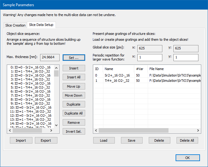
Setup a sequence of slices as it should be used during the multislice calculation from the entrance plane to the exit plane. The stack will be shown in the list on the left side, while slices available for stacking are listed on the right side.
In its upper part, the dialog denotes the sampling of the available slice data.
There are two edit boxes to set a periodic repeat along the x- and y-axis. This repetition can be used to increase the number of pixels of the calculated wave function beyond the present sampling of the projected potentials, e.g. to increase the number of pixels sampling the bright-field disk in CBED simulations. Use this option with utmost care, i.e. use only small numbers.
Available slice phase gratings listed on the right are identified by ID numbers as shown in the first column of the list. Further, a slice name, the number of frozen-lattice variants, and a file name may be displayed. The slice name denotes the composition of the slice.
The object slice sequence on the left side is a sequence of phase grating IDs and determines the sequence of the slices applied in the multislice calculation. Use the set of buttons between the lists to manipulate and build the sequence.
The length of the object slice sequence determines the maximum sample thickness of the calculation, which is denoted in the info box above the list. A longer list will not cause increased memory consumption but will result in longer calculation times.
The easiest way of setting up a thick sample is to use the [Set ...] button next to the Max. thickness display. You can set the desired sample thickness in nanometers and the program will fill the slice list on the left side with a periodic sequence of the slices on the right side.
Controls for individual slice stacking (left list)
[Insert]
The slices selected on the right side are inserted above the selected position on the left side. In order to insert selected slice at the end of the current sequence, undo any selection in the left list. You can toggle selections individually by mouse clicking the respective item while holding the Ctrl (Strg) key.
[Insert All]
All slices on the right side are inserted above the selected position on the left side. The slices are appended to the end of the object slice sequence if no selection is made in the left list.
[Move Up]
Slices selected on the left side are moved up by one position in the sequence towards the entrance plane.
[Move Down]
Slices selected on the left side are moved down by one position in the sequence towards the exit plane.
[Duplicate]
The slices selected on the left side are duplicated and inserted above the currently selected position into the slice sequence.
[Duplicate All]
All slices of the object slice sequence are duplicated. The complete object structure is thus repeated along the projection direction.
[Remove]
The slices selected on the left side are removed.
[Invert Sel.]
The selected slice sequence is reversed in its top-down order.
[Import]
Loads an object slice sequence from a text file.
[Export]
Saves the current object slice sequence to a text file. You may reload the sequence again later by using the [Import] function. You can also insert the content of the file at the respective position of a parameter file for the command-line program MSA.
Controls handling slice data (right list)
Slice data as listed on the right side can be loaded from disk files, saved to files, removed from the list, and merged to one slice. For each of these functions a respective button is present below the list. The list manipulation supports multiple selection.
[Load]
Slice files saved previously can be loaded and used again. You should check that the slice data corresponds to the current program parameters, especially to the current accelerating voltage. Take care to load only slice data, where all the slice have the same sampling and corresponding physical dimension. The slice-to-slice consistency in terms of sampling parameters is not checked by Dr. Probe.
[Save]
By saving slice data to files you may use them again later or by the command-line tool MSA.
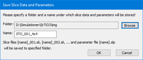
Select the desired destination folder and specify a unique file name. Existing files with equal file names will be replaced by the new files without asking your permission. Clicking the [OK] button to start the saving and wait until it is finished.
One file is saved for each slice with a file name is composed of the user specified name followed by a separator character (_), and a three-digit number identifying the position of the slice data in the list. One slice file may contain many slice variants as used for a frozen-lattice calculation. An additional collection of slice parameters is saved next to the slice files in form of a text file with extension '.slp'.
[Delete]
The slice data selected in the available slice data list will be unloaded from the working memory and the respective items will be removed from the list. Any slice inserted to the object slice sequence on the left side having the same ID as the removed item, will be removed automatically.
[Delete All]
All slice data will be unloaded and both lists, the object slice sequence and the available slice data will be empty afterwards.
Last update: Jan 28, 2019 contact disclaimer(de)