
|
GUI - Calculation Section > Dr. Probe / Documentation / GUI |
|
The calculation section of the main dialog provides controls to setup and run multislice simulations.
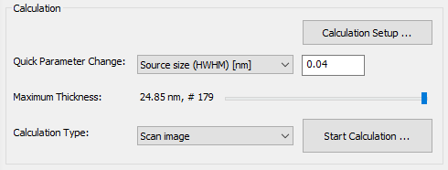
Most of the calculation parameters are set from the Calculation Setup dialog, which opens when pressing the respective button. There you will find general parameters concerning the calculation, for setting the scan frame, and precession angles.
Important simulation parameters, such as the effective source size, the illumination aperture, the probe defocus, and sample mistilt can be set directly in this section. Select the parameter from the Quick Parameter Change list and edit the values.
The object thickness slider allows you to select the maximum sample thickness between zero and the maximum thickness previously defined in the sample setup. The next multislice calculation will be performed only up to the this selected thickness. By default this slider should be set to its rightmost position. It may be used to quickly reduce the sample thickness for speeding up test simulations.
Before starting a multislice calculation you should select the calculation type from the dropdown list just left to the button labeled [Start Calculation ... ]. Three calculation types are supported (version 1.9.2):
- Scan image,
- Probe propagation & CBED, and
- Precession diffraction.
Scan image calculations involve a multitude of multislice calculations for a set of probe positions distributed equidistantly over a rectangular scan frame. Scan images can be calculated simultaneously for a periodic sequence of object thicknesses up to the selected maximum thickness, showing the integrated signal for each detector defined by the detector setup. The calculations are done on a user defined number of CPU cores and on a GPU device in parallel, which may significantly reduce the calculation time if many cores are available.
Calculations of the probe propagation through the sample, CBED pattern, and precession diffraction are done for a fix probe position and with the sampling used for describing the electron wave function. The current probe position is denoted by a white cross in the object data display window and can be changed by mouse click and moving. Alternatively, the probe position can be set explicitly by the scan frame offset in the calculation setup.
Probe intensity distributions are calculated for a periodic sequence of object thicknesses up to the selected maximum thickness. These calculations may include explicitly averaging over thermal atom vibrations (Einstein model), a geometric source distribution, and a defocus distribution in a Monte-Carlo approach.
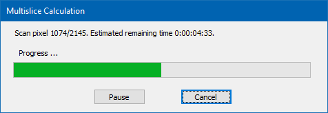
Calculations are started by pressing the respective button in the lower right corner of the calculation section. A dialog as shown above opens up informing you about the calculation progress and the estimated time until the calculation is finished.
Last update: Jan 27, 2019 contact disclaimer(de)